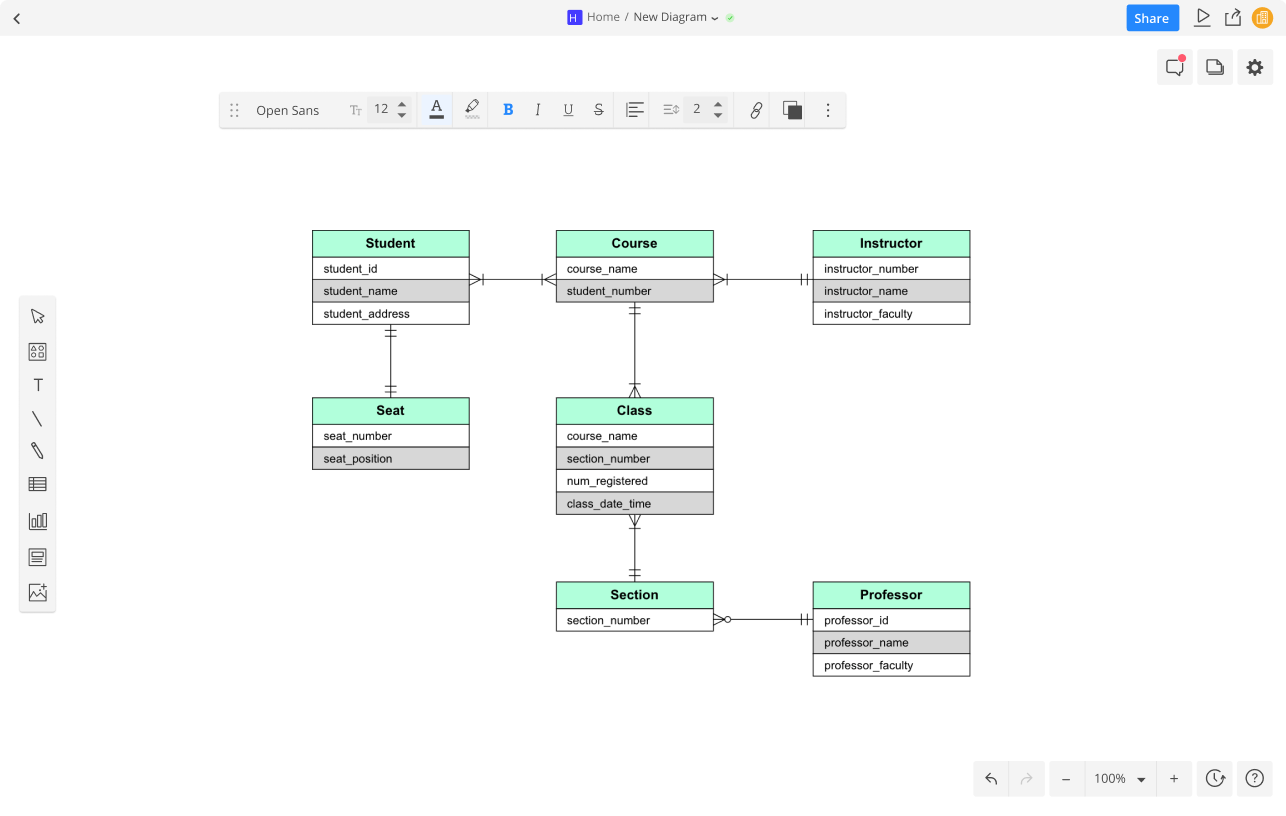
Dfd And ER Diagram – The ER Diagram can be a excellent tool for data mining. It allows the visualization of complicated relationships in a straightforward format. The basics are the identical regardless of the place you’re working. It starts by identifying “what” your system is. A rectangle is the symbol of the entity and should have ample space. Then, insert ovals for attributes and connect them to the entity. In the end, leave a space between rectangles and ovals.
Every single entity on the ER diagram is referred to as an attribute. An attribute is a characteristic, trait, or characteristic for an item. In the case of an ER diagram it is an Inventory Item Name is one of the attributes for the entity inventory Item. The entity may have any number of attributes it requires, and each attribute has its own specific attributes. For instance, a customer’s address can be identified by the following attributes: street number or city. Or state. These are composite characteristics, which means there aren’t restrictions on the quantity of each.
The next step in analyzing an ER diagram is to determine the amount of information that each entity has. The cardinality of an individual is the number of variables that exist between two entities. For instance, a consumer could purchase several phones through the same cell phone service while the provider of the service maintains several phones under only one bill. The ER diagram will make it easier to identify how the entities are connected. In addition, it can assist in determining the type of data that connects the various entities.
As the system develops and becomes more complicated The ER diagram could become congested and difficult to comprehend. The complex nature in an ER diagram requires more detailed representation on a micro-level. A properly designed ER diagram can help you get a better understanding of a system far more precise manner. Remember to add white space between tables in your ER diagram to ensure that there is no confusion. If you don’t, it will be difficult to discern the connection between two different entities.
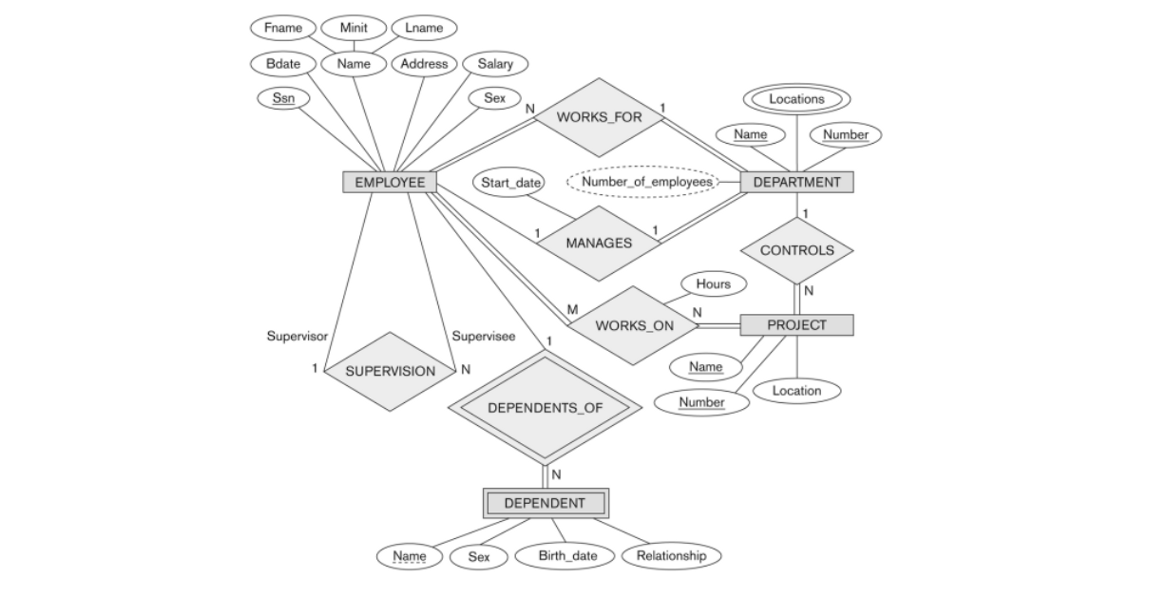
A person is an individual. An entity is an object or a class. An entity can be a person an individual, a city, or an institution. A weaker entity is one that is dependent to another and has none of the primary attributes. An attribute describes a property or characteristic of an object. The person in the ER diagram is an adjective. The city, too, is an entity. Hence, a connection exists between an entity is an adjective.
The attributes that make up the ER diagram need to be labeled. For example, a teacher entity could have multiple values for a subject. A student can be a part of multiple subjects. The relation between two individuals is represented by diamond-shaped shapes. Usually, these lines will be identified by verbs. They are then known as entities. If a student is confused regarding the meaning behind an attribute then the ER diagram can assist them in understanding the relationship between two things.
Get Dfd And ER Diagram