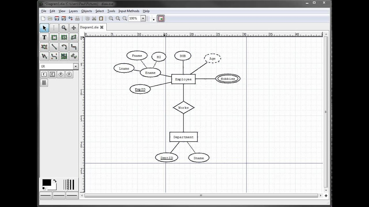
Drawing ER Diagrams – It is believed that the ER Diagram can be a useful tool for data mining. This is because it lets users to see complicated relationships in a straightforward format. The basic steps are the same regardless of where you’re working. The first step is identifying “what” your system is. A rectangle is the symbol of the entity and needs to be provided with plenty of room. Then, you can insert ovals for attributes and connect them to the entity. In the end, leave a space between your rectangle and an oval.
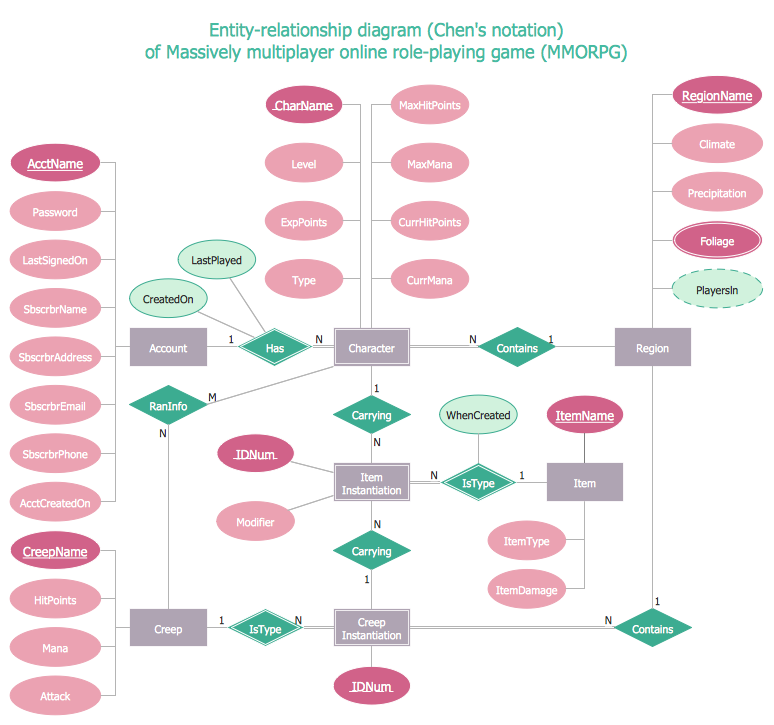
Every single entity on an ER diagram is referred to as an attribute. The term “attribute” refers to a property, trait, or characteristic for an item. In the case the case of an ER diagram an inventory Item Name is one of the attributes for the entity inventory Item. The entity may possess as many attributes as it requires. Each attribute may have particular characteristics. For instance, a customer’s address could have the attributes of a street number or city. It could also have a state. These are composite attributes and there’s no limit on the amount of each.
The next stage in the analysis of an ER diagram would be to determine the amount of information that each entity holds. The cardinality of each company is defined as the number of elements that are shared between two entities. For instance, a consumer can purchase multiple phones from the same service on one phone, and the cell phone provider may have multiple phones on one bill. The ER diagram can make it simpler to see the connections between entities. In addition, it may help you determine what the data is that connects all the entities.
As the system develops and gets more complex the ER diagram could become dense and difficult to understand. The complex nature of an ER diagram demands a more detailed representation at the micro-level. A properly designed ER diagram will assist you to comprehend a system in a more thorough manner. It is important to include white space between the tables of your ER diagram to keep from confusion. If you don’t do this, it could be difficult to determine the connection between two entities.
A person is a person. An entity is an object or a class. An entity can be an individual or a city or an organisation. A weaker entity is one that relies on another, and is deficient in the essential characteristics. An attribute defines a property that an item has. The person depicted in the ER diagram is a noun. In the same way, the city exists as an instance. So, the connection between two entities is a noun.
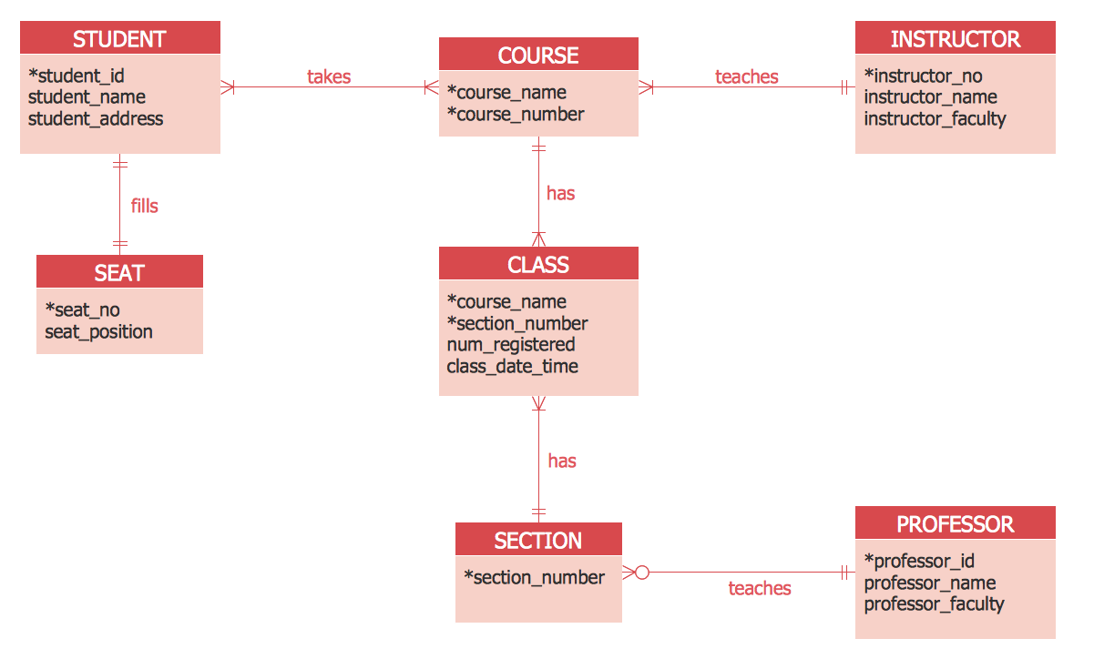
The characteristics included in an ER diagram must be identified. For instance, a teacher entity could have multiple subject-related values. A student can be a part of multiple subjects. The relation between two entities is symbolized by diamond shapes. In general, these lines are designated with verbs. Then, they are called entities. If a student has doubts regarding the meaning behind an attribute or a term, the ER diagram will help them understand the relationship between two things.
Get Drawing ER Diagrams