ER Diagram Description Example – It is believed that the ER Diagram can be a fantastic tool to use in data mining. This is because it lets the visualization of complicated relationships in a straightforward format. The fundamental steps are the same no matter where you’re working. It starts by identifying “what” your system is. A rectangle represents the entity, and it should be given ample space. After that, add ovals to represent attributes and join them to the entity. In the end, leave a space between rectangles and ovals.
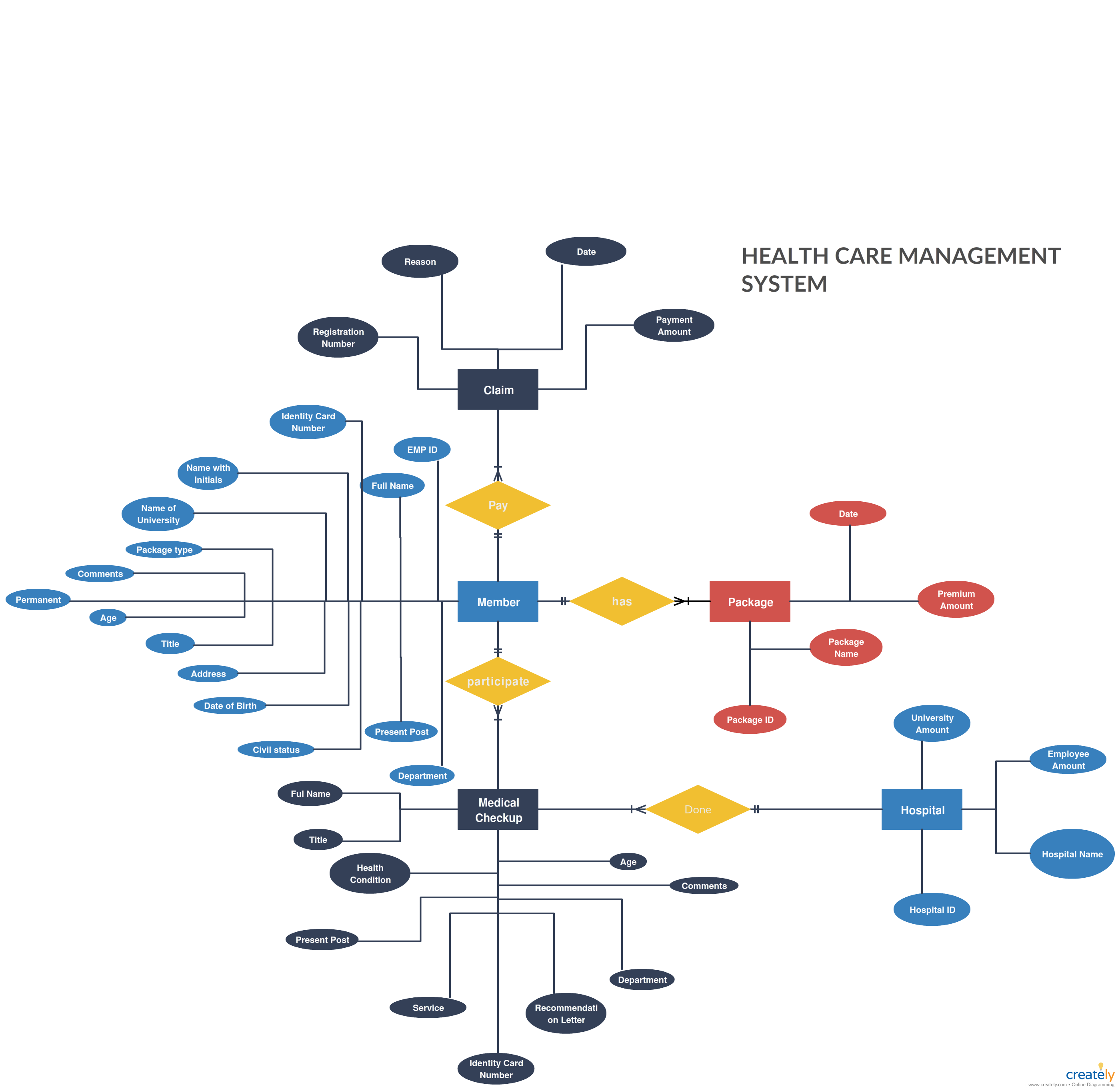
Every element on an ER diagram is called an attribute. An attribute is a characteristic, trait, or characteristic or characteristic of an object. In the context in an ER diagram, an Inventory Item Name is an attribute that belongs to the inventory of an entity Item. The entity may possess as many attributes as it requires, and each attribute may possess specific attributes. For instance, a client’s address may include the following attributes: street number, city, and state. These are composite attributes, which means there aren’t restrictions on the quantity of each.
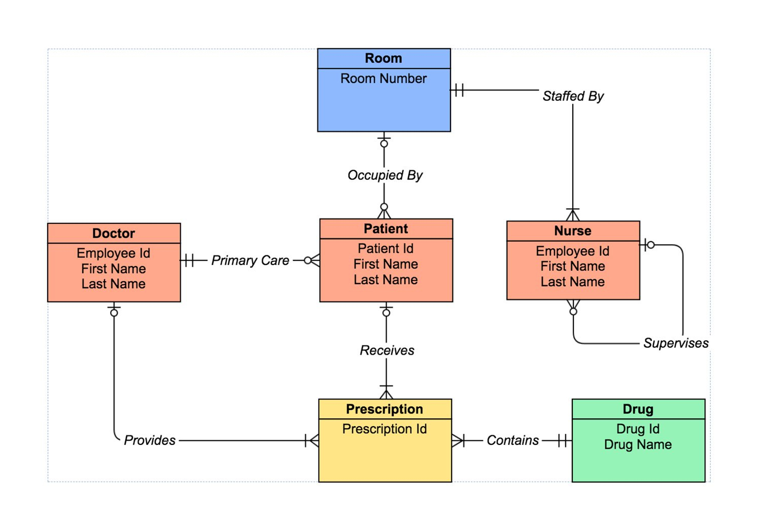
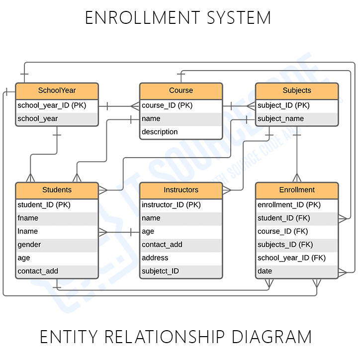
The next step in analyzing an ER diagram would be to determine the amount of information each entity has. The cardinality of every person is the number of factors that exist in between the two organizations. For instance, a consumer could purchase several phones through one phone service while the cell operator maintains many phones with one bill. The ER diagram could make it easier to recognize the relationship between entities. Furthermore, it could assist you in determining the information that links each entity together.
When the system is growing and gets more complex as it gets more complex, an ER diagram could become congested and difficult to comprehend. The complex nature of an ER diagram calls for a more thorough representation on a micro-level. A properly designed ER diagram will allow you to get a better understanding of a system far more precise manner. Just remember to include white space between the tables of your ER diagram to ensure that there is no confusion. If you don’t, it will be difficult to determine the connection between two different entities.
An individual is an entity. An entity is an object or a class. An entity could be an individual an individual, a city, or an organization. A weaker entity is one that is dependent on another, and is deficient in the primary characteristics. A property is described as an attribute that an item has. The person who is in the ER diagram is a noun. As well, the city itself can be described as an individual. The reason why a connection is established between two entities is an adjective.
The attributes within the ER diagram need to be labeled. As an example, a teacher entity could have multiple value for each subject. Students can also have many subjects. The relation between two entities is symbolized in the form of diamonds. Usually, these lines are designated with verbs. They are then known as entities. If a pupil is confused on the meaning of an attribute or a term, the ER diagram will assist them in understanding the relationship between two different objects.
Get ER Diagram Description Example