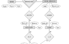
ER Diagram For Bug Tracking System – It is believed that the ER Diagram can be a useful tool for data mining. This is because it allows the visualization of complicated relationships in a straightforward format. The fundamental steps are the identical wherever you work. The first step is identifying “what” your system is. A rectangle is the symbol of the entity, and it should be given ample space. Add ovals to the attributes and connect them to the entity. In the end, leave a space between each rectangle.
Every element on an ER diagram is referred to as an attribute. Attributes are property or trait of an entity. In the case for an ER diagram it is an Inventory Item Name is one of the attributes of the entity Inventory Item. The entity may possess as many attributes as it requires. Additionally, each attribute could have distinct attributes. For instance, a client’s address could have the attributes of a street number or city. Or state. These are composite characteristics, and there’s no limit in the amount of each.
The next step to analyze the ER diagram would be to understand the amount of information that each entity contains. The cardinality of an organization is the number of elements that are shared among two different entities. For instance, a client might purchase multiple phones using one service for cell phones, while the provider of the service maintains numerous phones on only one bill. The ER diagram could make it easier to determine the links between the entities. Additionally, it will assist in determining what the data is that links each entity together.
As the system gets bigger and becomes more complex as it gets more complex, an ER diagram could become complicated and confusing to comprehend. The complex nature in an ER diagram demands a more precise representation on a micro-level. A properly designed ER diagram can help you comprehend a system in a greater depth. Remember to add white space in between tables in your ER diagram to keep from confusion. If you don’t do this, it could be difficult to discern the relationship between two different entities.
A person is a person. An entity is an object or class. An entity can be an individual, a city, or even an organization. A weaker entity is one that relies on anotherentity, but lacks the most important characteristics. An attribute is a description of a characteristic in an object. The person depicted in the ER diagram is a noun. Similarly, the city exists as an instance. Thus, a connection between an entity is a noun.
The attributes included in an ER diagram should be labeled. As an example, a teacher entity could have multiple value for each subject. A student entity can have several subjects. The relation between two individuals is represented in the form of diamonds. The lines are usually labeled with verbs. Then, they are referred to as entities. If a pupil is confused on the meaning of an attribute and is unsure of its meaning, the ER diagram can help them understand the relationship between two different objects.


