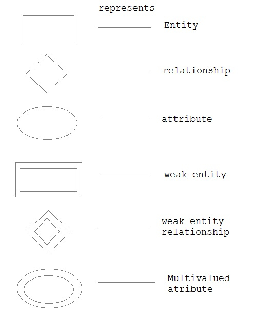
Symbols Used In ER Diagram In Dbms – The ER Diagram can be a great tool in data mining. This is due to the fact that it allows you to visualize complicated relationships in a straightforward format. The basic steps are the identical regardless of the place you’re working. It starts by identifying “what” your system is. A rectangle represents the entity and must be given plenty of room. Incorporate ovals as attributes and link them to the entity. Then, leave some space between your rectangle and an oval.
Every single entity on the ER diagram is known as an attribute. An attribute is a characteristic, trait, or characteristic in an organization. In the case that of an ER diagram an inventory Item Name is an attribute that belongs to the inventory of an entity Item. The entity may possess as many attributes as it requires. Additionally, each attribute may have its own specific attributes. For instance, a customer’s address can be identified by the attributes of a street number, city, and state. They are composite attributes which means there aren’t restrictions on the amount of each.
The next stage in the analysis of an ER diagram is to determine how much information each entity is able to provide. The primary characteristic of every individual is the number of factors that exist in between the two organizations. For instance, a customer could purchase several phones through one phone service however, the cell service provider has numerous phones on one bill. The ER diagram could make it simpler to see the relationship between entities. Additionally, it will aid in determining what the data is that connects all the entities.
As the system develops and becomes more complicated, an ER diagram may become complex and complicated to comprehend. The complex nature that comes with an ER diagram requires more detailed representation of the micro-level. A properly designed ER diagram will help you understand a system in a more thorough manner. It is important to include white space between tables in your ER diagram to avoid confusion. If you don’t, it’ll be difficult to identify the connection between two entities.
An individual is an entity. An entity is an object or class. An entity could be an individual one, a municipality, or an institution. A weaker entity is one that relies on another, and is deficient in the fundamental attributes. A property is described as an attribute that an item has. The person who is in the ER diagram is a noun. As well, the city itself exists as an instance. Thus, a connection between an entity is an adjective.
The characteristics of the ER diagram should be labeled. For instance, a teacher entity could have multiple subjects. A student entity can have many subjects. The relationship between two parties is represented by diamond-shaped shapes. These lines are typically described by verbs. Then, they are known as entities. If a student is confused regarding the meaning of an attribute, the ER diagram will assist them in understanding the relationship between two objects.
Get Symbols Used In ER Diagram In Dbms